robotics and automation system Germany Frankfurt am Main and Hesse companies
Table of Content
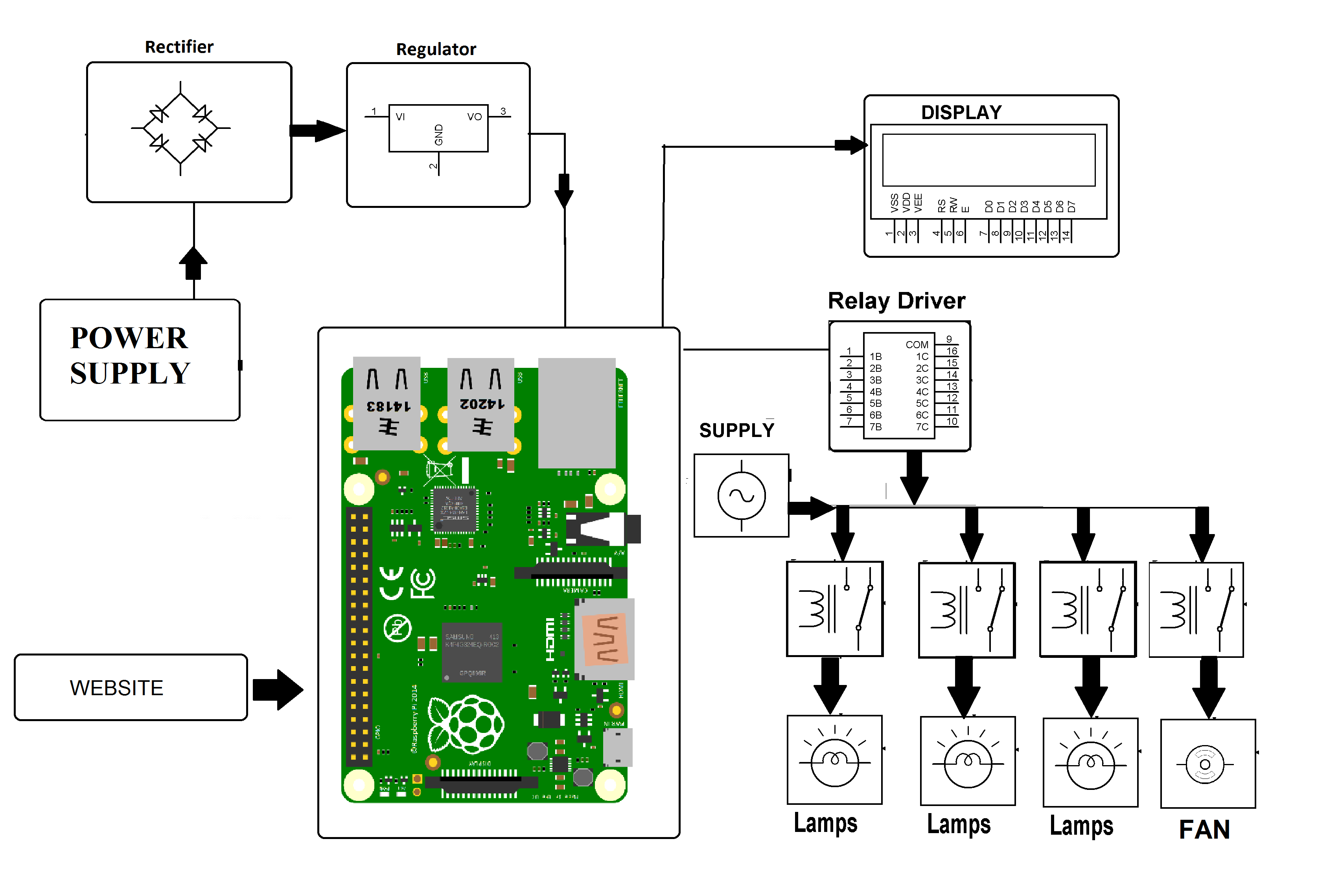
GSM module’s pin Tx and Rx is directly connected with Rx and Tx pins of Arduino. And power supply adaptor is also connected with GSM module. The ground of both GSM and Arduino should be connected with each other otherwise system will not work properly. Andrelaysare connected to digital pin 10, 11, 12 of Arduino for controlling light 1, light 2, TV respectively using ULN 2003 IC. ULN2003 is a high-voltage high-current Darlington transistor arrays.

16×2 LCD’s commands pins RS and EN is directly connected with pin 7 and 6 respectively and Data pins d4, d5, d6, d7 are connected with 5, 4, 3, 2 pins of Arduino. First, we start by including the software serial library, which will be used to establish communication between the HC-05 Bluetooth module and the app. If there is any error in the data transmission i.e. the desired data is not transmitted, the Arduino at the receiver section lights up the error LED which is connected to the 13th pin.
RF BASED SMART HOME AUTOMATION SYSTEM © GPL3+
First, we need to pull down the digital I/O pins 3 through 6 with the help of four 1KΩ resistors. Then connect four switches to these four pins with the other ends of the switches connected to 5V supply. We have previously explained the RF Transmitter and Receiver circuit in detail. Thanks to the quality BVS has been consistently striving towards for decades, we now work with several large control and drive manufacturers. As the only company worldwide working in the industrial electronics maintenance sector, we carry our status as "Bosch Rexroth Group Service Point", among others, with pride.
Next, make a function to auto-connect to the HC-05 Bluetooth module when the screen is initialized. If the connection is successful, we show an alert, saying that the connection was successful. Create a variable text to store the text of our speech, if the speech recognition button is clicked. Make a table arrangement with 3 rows, and add a label to each row, for individual lights.
Step 5: Example: Light Sensor
The RF Receiver receives the data through RF links and must transmit this data to the Arduino. Hence, the data out pin of the receiver module must be connected to digital I/O pin 11 of the Arduino. A relay board consists of all the components that are required for a relay to be operated by a microcontroller. A four channel relay board is used although only two relays are used in the practical implementation.
AutoCAD is a commercial computer-aided design and drafting software application. In the previous tutorial on 8051 Microcontroller, we have seen the 8051 Microcontroller Introduction and Basics, Pin Diagram, Pin Descripti... First, add all the non-visible components - the speech recognition, the Bluetooth client, and the notifier.
Hi , i am using the relay and
At the receiver end, the RF receiver receives this message and transmits the same to Arduino for decoding. When the Arduino at the receiver end decodes the message and understands that the transmitter characters are “@ABC$”, it then writes a HIGH signal on the digital I/O pin 4. If you are using a relay board, as we are in this project, simply connect the digital I/O pins 4 and 5 of the Arduino to the input pins of the relay. We will utilize this by creating the voltage divider from the photorestior and a 10k ohm resistor. Start by wiring the 10k ohm resistor and the photoresistor in series.
We will need a variable to store the message received by the HC-05 module, and variables mentioning the pins to which the LEDs are connected. Connect one terminal of the AC power supply to one terminal of the load. Connect the other terminal of the load to the common pin on the relay.
Filed Under: Electronic ProjectsTagged With: Arduino, gsm, home automation
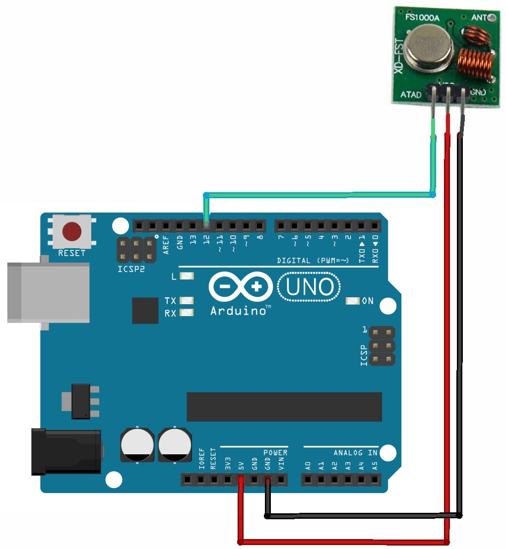
The first component we need to connect to the Arduino UNO is the RF Transmitter module. The data in pin of the RF Transmitter module is connected to the 8th digital I/O pin of Arduino. VCC and GND are connected to 5V and ground pins of the Arduino respectively. An optional antenna wire can be connected to the antenna pin of the transmitter module. After the decoder receives the value of D13 is also makes its D11 pin to be zero.
I removed the copy/paste code and attach it as complete INO file. As stated in the introduction there's a lot of possibilities with an Arduino and the know-how to control RF signals. I used a photo resistor as a sensor to detect the light level in my room. Arduino IDE software has been used to compile some programs related to the micro controller ATmega328.
The address pins 1 to 8 of the decoder IC HT12D are hard wired to ground in order to match the 0x00 address of the RF transmitter. IAI is a leading supplier of components and system solutions for pneumatic-free automation technology. For more than 40 years, the company has been developing and producing energy-saving electric actuators and industrial robots. Not least because of this, the product range is now considered the most comprehensive on the market.
Connect 5V from the microcontroller at the 10k ohm resistor, and connect GND to the open end of the photoresistor. Now, we can read the change in voltage by connecting a wire to the junction where the 10k ohm resistor and the photoresistor connects. To use a photoresistor as a light sensor we need to create a voltage divider. A photoresistor works by changing resistive value based on how much light is hitting the resistor.
LCD used with arduinofor displaying the appliances status and process like SYSTEM READY, TV ON, light 1 ON, light 1 OFF, light 2 ON, light 2 OFF etc. In which one zero watt bulb indicated by light 1 and second is 100 watt bulb indicated by light 2 and third and last is TV/LCD indicated by TV. In system has an additional function in which you will get the notification or status message on message sending number. Means if you sends message for ON OFF any electrical appliance by any mobile number then you will get status or notification message on the same mobile number. The VCC and GND pins of the receiver module are connected to 3.3V and ground pins of the Arduino. An antenna can be connected to the antenna terminal of the module.
Simply power on both the modules with the corresponding voltage mentioned above. Now, make the Din pin on transmitter high and you will find the Dout pin on receiver also goes high. You can have only one button on the sender side and one output on the receiver side. This will not help in building better projects, so we employ the encoder and decoder modules.
The design of the circuit is explained with respect to transmitter section and receiver section individually. The circuit diagram is divided in to the transmitter section and receiver section for easy understanding. The transmitter section of the project is shown on the following image. In this project, a simple but efficient home automation system using RF Module (Transmitter – Receiver pair) is designed. The system is designed with Arduino as the main processing unit.

The remote controller circuit is just the RF transmitter section. The circuit connections of RF module are done as in set up of the basic model of RF Transmitter and Receiver. The address pins 1 to 8 of the encoder IC are hard wired to ground to assign the RF transmitter an address of 0x00. The pin 14 of the encoder IC which is active low is also hard-wired to ground to enable uninterrupted transmission of control signal to the RF receiver. The project RF based home automation system is developed to automate the use of conventional lighting mechanism in house by using RF controlled remote.


Comments
Post a Comment