Introduction to Home Automation With Arduino and RF Signals! : 7 Steps with Pictures
Table of Content
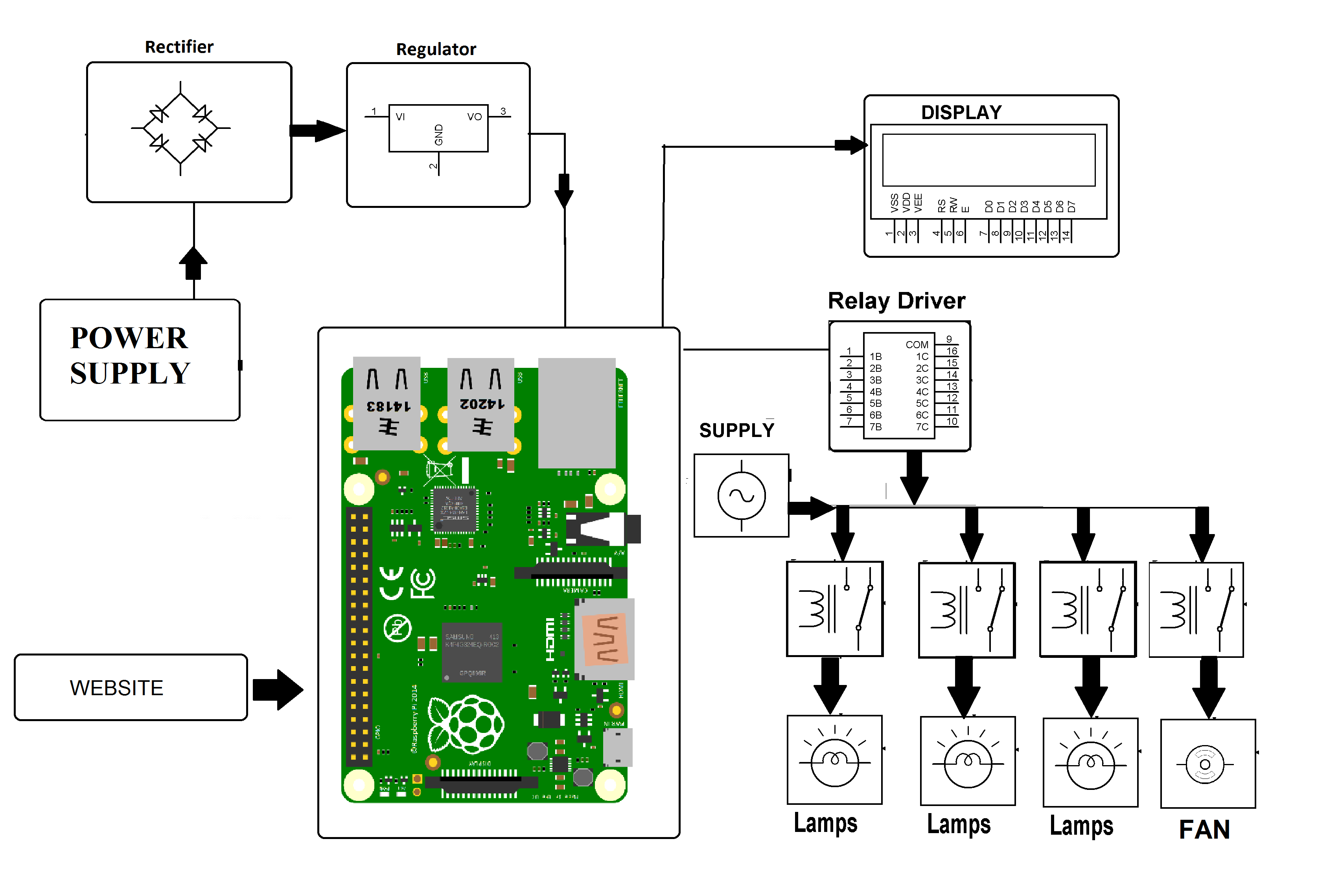
16×2 LCD’s commands pins RS and EN is directly connected with pin 7 and 6 respectively and Data pins d4, d5, d6, d7 are connected with 5, 4, 3, 2 pins of Arduino. First, we start by including the software serial library, which will be used to establish communication between the HC-05 Bluetooth module and the app. If there is any error in the data transmission i.e. the desired data is not transmitted, the Arduino at the receiver section lights up the error LED which is connected to the 13th pin.

The other methods of remote controlled home automation system are ZigBee, Wi-Fi, Radio Frequency , GSM etc. Semicon Media is a unique collection of online media, focused purely on the Electronics Community across the globe. With a perfectly blended team of Engineers and Journalists, we demystify electronics and its related technologies by providing high value content to our readers. Hi , i am using the relay and that is connected to a bulb. But when i send a signal through a raspberry pi rather than doing using classic switches my relay is not reponding. Whereas in the receiver side we have used a 7805 +5V voltage regulator to regulate 5V from the 9V battery.
Electronics Project Categories
The project requires a RF remote that is interfaced to microcontroller on transmitter side which sends ON/OFF signals to the receiver. Receivers are connected with loads that can be turned ON/OFF by operating remote switches on transmitter wirelessly. At the relay circuit, an RF receiver is used and the loads are connected at the data pins 10 to 13 designated as D0 to D3 of the decoder IC HT12D through the relays.

Note the light levels at which you want your light or LED panel to turn on and off. Enter these values in line 9 and 10 to calibrate the code for your room. Here the loads are interfaced to microcontroller by utilizing opto-isolators and triacs.
Volt Battery Charging System
We can also build this circuit without using a relay module. In that case you would have to use an additional transistor like BC547 and drive it using a current limiting resistor to its base. Now, open up the serial terminal and press any button on your RF remote to decode the signals. The information that pops up in your serial terminal is what we'll be transmitting later on. The main objective of this project is to develop a smart home automation system with a button key fob transmitter by using RF.
With the help of program, we are implementing the encoder and decoder actions in Arduino. Similar actions are performed when other switches are pushed. As a result, the relay connected to load 1 is activated and the load is turned on. The 434 MHz Radio Frequency Transmitter – Receiver Module is the best and cheapest way to implement a wireless communication for a reasonably longer ranges.
Things used in this project
You can now play around this set-up by toggling your switches and your AC loads should also be toggled accordingly. The range of these modules could extend by using antenna on the transmitter module. The Transmitter module consists of three pins namely Vcc, Din and ground as shown above. The Vcc pin has a wide range input voltage from 3V to 12V.
Simply power on both the modules with the corresponding voltage mentioned above. Now, make the Din pin on transmitter high and you will find the Dout pin on receiver also goes high. You can have only one button on the sender side and one output on the receiver side. This will not help in building better projects, so we employ the encoder and decoder modules.
Step 3: Transmitter Circuit Diagram
We will need a variable to store the message received by the HC-05 module, and variables mentioning the pins to which the LEDs are connected. Connect one terminal of the AC power supply to one terminal of the load. Connect the other terminal of the load to the common pin on the relay.
This four button key fob transmitter is also very productive for commercial uses in Industrial and medical systems. Remote controlled home automation system provides a simpler solution with RF technology. As technology is advancing so houses are also getting smarter. Modern houses are gradually shifting from conventional switches to centralized control system, involving RF controlled switches. Presently, conventional wall switches located in different parts of the house makes it difficult for the user to go near them to operate. Even more it becomes more difficult for the elderly or physically handicapped people to do so.
First, we need to pull down the digital I/O pins 3 through 6 with the help of four 1KΩ resistors. Then connect four switches to these four pins with the other ends of the switches connected to 5V supply. We have previously explained the RF Transmitter and Receiver circuit in detail. Thanks to the quality BVS has been consistently striving towards for decades, we now work with several large control and drive manufacturers. As the only company worldwide working in the industrial electronics maintenance sector, we carry our status as "Bosch Rexroth Group Service Point", among others, with pride.
Thus the system serves a convenient way of lighting up the house without any physical movements. As mentioned earlier, we will be using two 5V relay module to control the AC loads. The term “5V” here represents the voltage required to trigger the relay. Out of the 4-data bit we will use only two in this project for demonstration purpose. You can use all four and control four AC Appliances with the same circuit. The Receiver module has four pins namely Vcc, Dout, Linear out and Ground as shown above.
The portfolio includes electric mini cylinders, linear actuators, servo presses, rotary drives as well as electric grippers. In addition, there is an extensive range of Cartesian robots, table-top robots and SCARA robots for automated production. In addition to the standard version, many products are also available as dust- and water-protected models with corresponding IP protection classes or as cleanroom versions.
Today I'm going to show you an introduction on home automation with RF signals. Itshows communication between the RF Transmitter and the RF receiver and the display on the LCD .Arduino Uno R3 was used. Maker.pro needs to review the security of your connection before proceeding. Sign up and receive our weekly newsletter for latest Tech articles, Electronics Projects, Tutorial series and other insightful tech content. Arduinois the heart of this system which takes control over whole the system process.
In the void setup, we set up the serial monitor and virtual Bluetooth serial at 9600 baudrate. The receiver section of the project is shown in the following image. Sensirions’s SCD4x product line combines minimal size with high performance and easy assembly. Hope you liked the project and enjoyed building something similar. If you have any doubts you can post them on our forums or on the comments below.
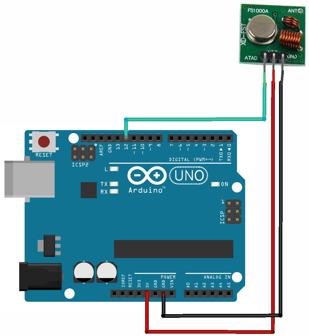
The first component we need to connect to the Arduino UNO is the RF Transmitter module. The data in pin of the RF Transmitter module is connected to the 8th digital I/O pin of Arduino. VCC and GND are connected to 5V and ground pins of the Arduino respectively. An optional antenna wire can be connected to the antenna pin of the transmitter module. After the decoder receives the value of D13 is also makes its D11 pin to be zero.


Comments
Post a Comment